Wheel Failure Modes: What FEA Can Screen For and What It Cannot
Five ways a forged wheel fails in service, and for each, whether a static FEA design check can catch it before release or whether it needs testing and process control.
When a forged wheel cracks, bends or comes loose, the cause usually traces back to one of a handful of mechanisms, each with its own root cause and its own point in development where it should have been stopped.
For a wheel brand, the useful question is not "how do wheels break?" but "which of these failures can I design out on screen, and which ones need a test rig, a process control or an installation instruction?" This post walks through the five failure modes that matter most and sorts them honestly.
The short version
| Failure mode | Typical origin | Static FEA design check |
|---|---|---|
| Fatigue crack | Spoke root, spoke-to-barrel transition | Finds where it will start; does not give a life |
| Impact fracture | Rim flange, outer spoke face | Not screened; needs an impact test |
| Spoke separation | Thin or abrupt spoke root section | Screened well |
| Barrel collapse | Barrel, bead seat, flange under radial load | Screened for the applied radial load |
| Hub clamping failure | Bolt seat, centre bore, torque | Not screened; installation and fitment control |
A static check is strongest where the failure is driven by a known load acting on a geometry that might be too thin or too sharp. It is weakest where the failure depends on a dynamic event, a material defect or how the wheel was fitted.
Failure mode 1: fatigue crack
Fatigue is the slow one. Cornering, braking and road input load the same features thousands of times. Where local stress is high enough, a microscopic crack initiates at a stress concentration and grows a little with each cycle. By the time it is visible, it may already run across the spoke root.
The usual origin is the spoke root and the transition into the barrel, close to the mounting face, where cornering bending concentrates. A root cause that keeps appearing is a wheel carrying more load than it was designed and tested for, so the cyclic stress sits too close to what the alloy tolerates.
What FEA can do. A static analysis under the vehicle's radial load and wheel torque shows where the stress peaks are and how high they are relative to yield. That is exactly the information you need to move a fatigue origin out of the danger zone: a larger fillet radius, more spoke depth or width at the root, a softer section change.
What it cannot do. A static check is not a fatigue-life calculation. It will not tell you how many kilometres or cycles a spoke survives. It tells you whether the peak stress keeps the required margin against yield, and where the weakest point is. Rotating-bending and radial fatigue tests on physical samples are still what qualify a specification.
Note For 6061-T6, LoudGears uses a yield strength of 313 MPa and a minimum safety factor of 3.0, so peak von Mises stress above roughly 104 MPa fails the check. For AZ80A-T6 magnesium the yield is 230 MPa with a minimum factor of 2.5 (3.0 recommended), a fail line of 92 MPa. See wheel material.
Failure mode 2: impact fracture
Impact fracture is sudden: a pothole at speed, a kerb strike, debris. A single high-energy load hits the rim flange or the outer spoke face. Forged 6061-T6 has a dense, continuous grain structure and tends to deform locally before it breaks, which is one reason forged wheels tolerate impacts better than cast wheels with porosity. Better is not immune; a hard enough hit at a bad angle breaks any wheel.
What FEA can do. Indirectly, a little. A flange or outer spoke face that already runs high stress under the static load case has less reserve left for an impact.
What it cannot do. A static radial-plus-torque check does not simulate a striker hitting the rim. Impact resistance is demonstrated by the impact test in the relevant wheel standard, on the physical wheel. Treat it as a separate gate.
Failure mode 3: spoke separation
A spoke separates from the hub pad or the barrel when there is not enough material in the transition, usually because the spoke was thinned to hit a weight or a look. A deep concave face with slim spokes can photograph beautifully and still put too little section where the bending moment is highest.
This is the failure a design check is best at. The load path from hub face to barrel runs straight through the spoke root, and a thin root shows up as a concentrated hotspot long before anything is machined.
What FEA can do. Screen it directly. If the root section is too small for the load, the peak stress and safety factor say so, and a rule-based design advisor can point to where material should go: a larger root fillet, more spoke depth or width, a locally thicker transition.
The practical lesson for a brand is the order of decisions: fix the load target first, then shape the face to it. A face design approved before the load is known tends to be defended rather than corrected.
Failure mode 4: barrel collapse
The barrel fails when radial load exceeds what the barrel, bead seat and flange can carry. It is mostly a problem of under-specified wheels on heavy vehicles, or wheels that see repeated hard impacts. Tyre choice matters: a low sidewall on a heavy car passes more impact energy into the barrel than a taller one, so the load the barrel sees in service can be well above the static weight.
What FEA can do. Check barrel, bead seat and flange stress under the applied radial load, and show whether a thin barrel section or a sharp bead-seat transition is the weak point. Locally thickening the barrel or bead seat is a standard advisor suggestion.
What it cannot do. It does not know the tyre profile, the road or how hard the driver hits a pothole. The check is valid for the load case that was applied. If your customers fit low-profile tyres on heavy cars, choose a load case with reserve, not the bare axle baseline.
Failure mode 5: hub clamping failure
The wheel is clamped to the hub by bolts or nuts at a specified torque. Too little torque and the wheel works loose; too much and the fastener stretches past its elastic limit. If the centre bore does not locate on the hub, the vehicle weight is carried through fasteners that were designed to clamp, not to act as load pins.
These failures are almost always fitting errors: wrong seat type (conical or ball), missing hub rings, wrong torque, no re-torque after the first drive.
What FEA can do. Very little. A structural check of the wheel body does not verify how the wheel will be installed.
What it cannot do. Replace correct seat geometry on the drawing, a centre-bore specification and clear fitting instructions in the box. This failure is controlled by documentation and process.
When the crack lands on the hotspot
A stress map is only worth trusting if it points at the places real wheels actually crack. In validation with a partner forged wheel manufacturer, road fractures were replayed blind, without telling the model where the crack was.
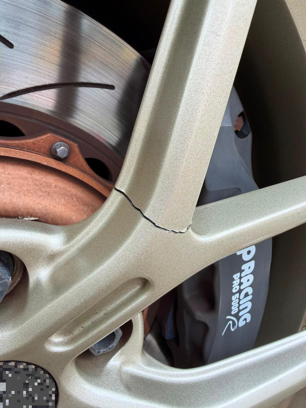
In Case 01, a spoke-root fatigue crack, the LoudGears peak hotspot of 139.2 MPa sat at the crack origin.
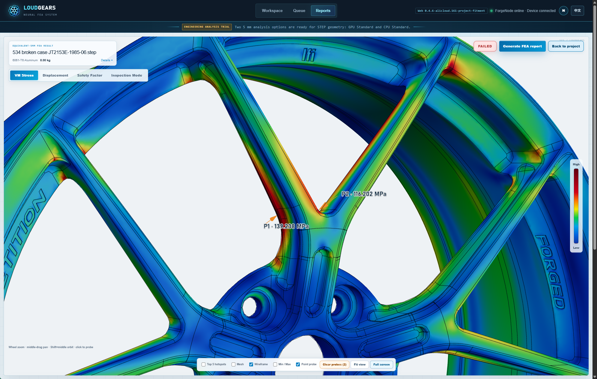
In Case 02, a wheel that fractured at both a spoke edge and a bridge, both hotspots were found, at 131.2 and 148.1 MPa. Both are well above the roughly 104 MPa fail line for 6061-T6, which is what you would expect from wheels that cracked.
Correlation is not a guarantee, but it shows that a check under realistic radial load and torque explains where failures start.
Where this fits in your release process
- Fix the load target per wheel from the vehicle, with reserve for tyre, use and road. See vehicle loads.
- Run the static design check on every face variant, read the hotspots and safety factor, and act on the advisor's material suggestions. See how to read a wheel FEA report.
- Send only checked designs to physical testing, which covers fatigue life and impact. See wheel testing standards vs FEA.
- Control fitment: seat type, centre bore, torque, re-torque instructions.
FEA moves fatigue, spoke and barrel problems to the cheapest point in the program, on screen. It does not replace the rig or the fitting instructions. If you want to see what a hotspot review looks like on a real wheel, try the demo.