Radial vs Combined Load FEA for Forged Wheels: What Changes
A radial-only FEA run can make a forged wheel design look comfortable when it is not. Here is how torque and side load move the stress, and what that means for release.
The question a radial-only run answers
Most wheel FEA starts the same way: fix the hub, push down on the bead seat with a share of the vehicle weight, and look at the colour map. That run is worth doing. It tells you whether the barrel, the spokes and the hub pad can carry vertical load, and it catches gross problems such as a spoke that is simply too thin.
What it does not tell you is how the wheel behaves when the load stops being a single, clean downward force. On the road the tyre contact patch is never only pushing up. Drive and brake torque try to rotate the rim relative to the hub. Cornering pushes the rim sideways and bends the spokes out of plane. Tyre pressure acts on the inside of the barrel the whole time. Each of these loads uses a different path through the wheel, and those paths do not all end at the same place as the radial path.
For a wheel brand, that is the important point. A radial-only run is a baseline, not a release check. If it is the only load case behind a design sign-off, the sign-off is answering a narrower question than the one the wheel will face.
What each load component adds
It helps to be explicit about what each part of the load case contributes and what it leaves out.
| Load component | What it exercises | What it misses on its own |
|---|---|---|
| Radial load | Vertical load path from bead seat through spokes to hub | Spoke twist, side bending, drive and brake transfer |
| Wheel torque | Rotational load from hub to rim; angular spoke deformation | Out-of-plane bending from cornering |
| Lateral load | Side bending of spokes and lip under cornering grip | Acceleration and braking |
| Tyre pressure | Constant pressure on the barrel and transition zones | Rarely dominant by itself |
| Combined | The interaction of all of the above in one solve | Harder to set up consistently and to interpret |
Torque is usually the one that changes the picture most for spoke design. Under pure radial load a spoke mostly bends in its own plane, along its deepest section. Under torque it is loaded sideways across its narrower section, and the stress collects where the spoke meets the hub or the barrel. That is exactly where designers like to put windows, pockets and styling grooves.
One sample review: 57.3 vs 167.1 MPa
A sample review shared by a partner forged wheel manufacturer shows the effect clearly. Same 6061-T6 wheel geometry, same material basis, same threshold. The only thing that changed was the load case.
| Load case | Peak von Mises stress | Safety factor (313 MPa yield) | Against the 3.0 line (about 104 MPa) |
|---|---|---|---|
| Radial only | 57.3 MPa | about 5.5 | Pass |
| Radial + torque + lateral + tyre pressure | 167.1 MPa | about 1.9 | Fail |
The radial-only result looked generous: peak stress at roughly 18% of yield, with a large margin to the fail line. Adding the other loads nearly tripled the peak, to about 53% of yield. That is still well below the point where the alloy would bend permanently in a single hit, but it is far above the level a forged aluminium wheel should run at for millions of road cycles.
These numbers come from that one sample review, not from a LoudGears benchmark. The lesson is not the specific ratio, which will differ for every design, but the direction: a design that passes comfortably under radial load can fail once the other loads are included.
The groove was the problem, not the alloy
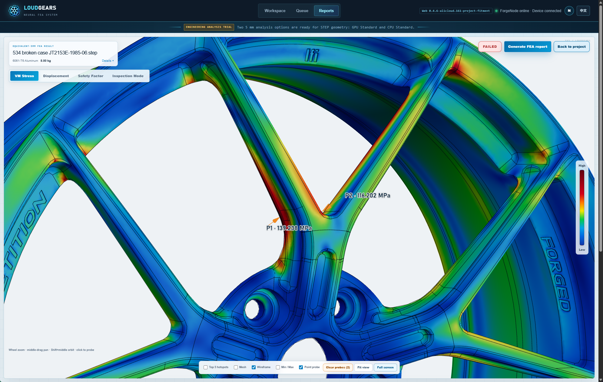
In the sample, the combined-load peak sat in a U-shaped groove at the spoke root, close to the barrel transition. In the radial-only run that groove was barely visible on the stress map. Under torque the spokes deformed angularly, and the groove became the place where the load had to turn a tight corner.
The fix was geometric. The groove was modified out, the stress path cleaned up, and the revised design passed its review before anything was machined. No material change, no extra mass added across the whole wheel. One local feature was creating the problem, and once it was gone the rest of the wheel was fine.
That is the most common outcome of a combined-load review. Materials rarely need changing. A fillet, a groove, a window edge or a thin bridge is concentrating stress in the wrong place, and the combined case is what makes it visible.
For a related example from real road use, see why forged wheels crack at the spoke root.
Building load cases you can release against
The harder part of combined-load FEA is not the solver. It is setting up the load case the same way every time, so that two engineers analysing two revisions of the same wheel get comparable answers. General-purpose CAE leaves that to the analyst: direction of torque, how the hub is supported, how the contact load is distributed. Small choices move the peak.
In LoudGears the load case starts from the vehicle. You pick make, model and generation, and the run applies a radial load and a wheel torque for that vehicle, using the same rules on every run. An approved manual override is available when you need to match a specific programme or a customer requirement. The applied loads are listed in the result and in the PDF report, so the reviewer can see exactly what the wheel was checked against. See vehicle loads for how they are chosen.
Whichever tool you use, a few habits make the review more trustworthy:
- Never sign off a design on a radial-only run. Treat it as the first screen.
- Record the load case with the result. A peak stress without its loads is not comparable to anything.
- Check the hotspot location, not only the safety factor. A good margin in a sensible place is different from a good margin by luck.
- Re-run the same load case after every geometry change, including cosmetic ones such as grooves, engraving depth and window shape.
- Use heavier vehicles as the design case when one design will be sold across several fitments. A heavy EV pushes far more torque through a wheel than a light hatchback.
What the material threshold means
The sample used 6061-T6 with a yield strength of 313 MPa and a minimum safety factor of 3.0, so the fail line sits at about 104 MPa. Keeping peak stress at a third of yield is not about a single overload. It leaves room for fatigue, for road inputs harsher than the nominal load case, and for the scatter between a model and a forged part.
For AZ80A-T6 magnesium, LoudGears uses a yield of 230 MPa with a minimum safety factor of 2.5 and 3.0 recommended, which puts the fail line at 92 MPa. See wheel material for how the verdict is set.
What FEA does not prove
A combined-load pass means the design stays inside the safety-factor limit for the load case that was applied. It is a design check, not a certification and not a fatigue-life figure. Physical tests such as JWL still apply only to the exact specification that was tested. For how the two fit together, see wheel testing standards vs FEA.
If you want to see how a vehicle-based load case looks on a real result, open the demo.